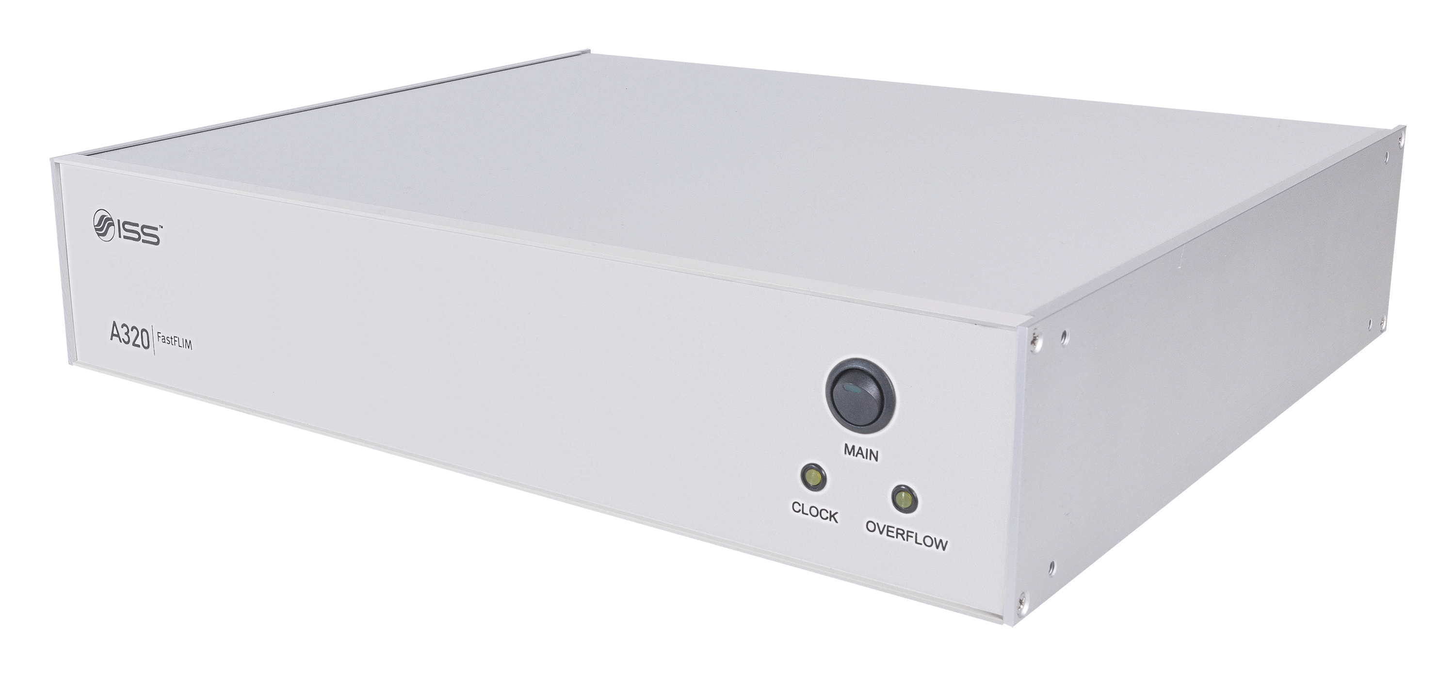
Overview of FastFLIM
FastFLIM is the data acquisition card for your FLIM acquisition when data acquisition time is of the essence. The card has been developed using the Digital Frequency Domain (DFD) technique that allows for the acquisition of Time-Tagged-Time-Resolved data without the dead time typical of the TCSPC approach. The four independent input channels can be configured for accepting signals from PMTs, APDs with TTL output, or a combination of the two types of detectors.
The design allows for maximum FLIM data acquisition of up to 80 x 106 counts/s per channel for two channels simultaneously, or 40 x 106 counts/s per channel for four channels simultaneously. Decay times from the picosecond to the second time scales can be resolved (FLIM and PLIM). In addition to the fitting analysis, the FLIM data acquired by FastFLIM can be directly used for phasor plots without any distortion. The card is supported by drivers in Windows 11, 64-bit, and communicates with the computer through the USB 3.0 protocol.
Features
- 4-channel simultaneous acquisition
- Direct input from PMTs and APDs (or a combination of the two)
- Photon count rate up to 1 x 10⁹ counts/s
- Dead time 1.56 ns
- Trigger out to synchronize external devices
- Trigger input from external source
- Line and Frame CLK synchronization
- USB communication
- Drivers for Windows 11, 64-bit
Applications
- Time-Tagged-Phase-Resolved lifetime measurements
- Single-wavelength FLIM, multi-wavelength FLIM
- Single-wavelength PLIM, multi-wavelength PLIM
- Confocal images
- Polarization images (steady-state and time-resolved)
- FCS, FCCS, PCH
- Scanning FCS, RICS, N&B
- Stoichiometry
- Single Molecule FRET
- PIE measurements
The FastFLIM unit is utilized in the FLIM & FFS upgrade kit for commercial laser scanning microscopes (LSMs) by Olympus, Nikon, and Zeiss. Also, it can be utilized as a stand-alone unit for assembling a custom-built FLIM instrument.
Product Specifications for FastFLIM
Architecture
- USB 3.0
CLK frequency
- 640 MHz
No. of INPUT channels
- 4 independent channels
Input voltage range
- From PMTs and/or APDs (-1V ~ +5V, 50 Ω)
Decay times measurement
- PLIM and FLIM: 100 ps to 100 ms
Dead Time
- 1.56 ns
External CLK IN
- 10 ~ 80 MHz (LVTTL / TTL, 50 Ω)
Reference CLK OUT
- 0.0596 Hz – 80 MHz, Amplitude: + 1.2 & 1.8 V (50 Ω)
Reference SYNC OUT
- 20 MHz 50% duty cycle, Amplitude: + 2.5 V (50 Ω)
LINE/FRAME/PIXEL Scan
- Synchronization w/ scanner
Data handling and storage
- Acquisition of raw data for FCS, FCCS, PCH, smFRET, burst.
- On-line processing or post-processing
Raw data size
- 32 bits
Raw data file structure
- Binary file with a header of 256 bytes
Max Signal in Counts (Steady-state Intensity Only)
- 109 counts/s
(250 x 106 counts/s per channel for four channels simultaneously)
Max Signal in FCS & FLIM (time tagged & time tagged time resolved – TTTR)
- 160 x 106 counts/s
(80 x 106 counts/s per channel for 2 channels simultaneously)
(40 x 106 counts/s per channel for 4 channels simultaneously)
Power
- 120/240 V, 50/60 Hz, 40 W
Dimensions (cm)
- 42.5 (W) x 36 (D) x 10 (H)
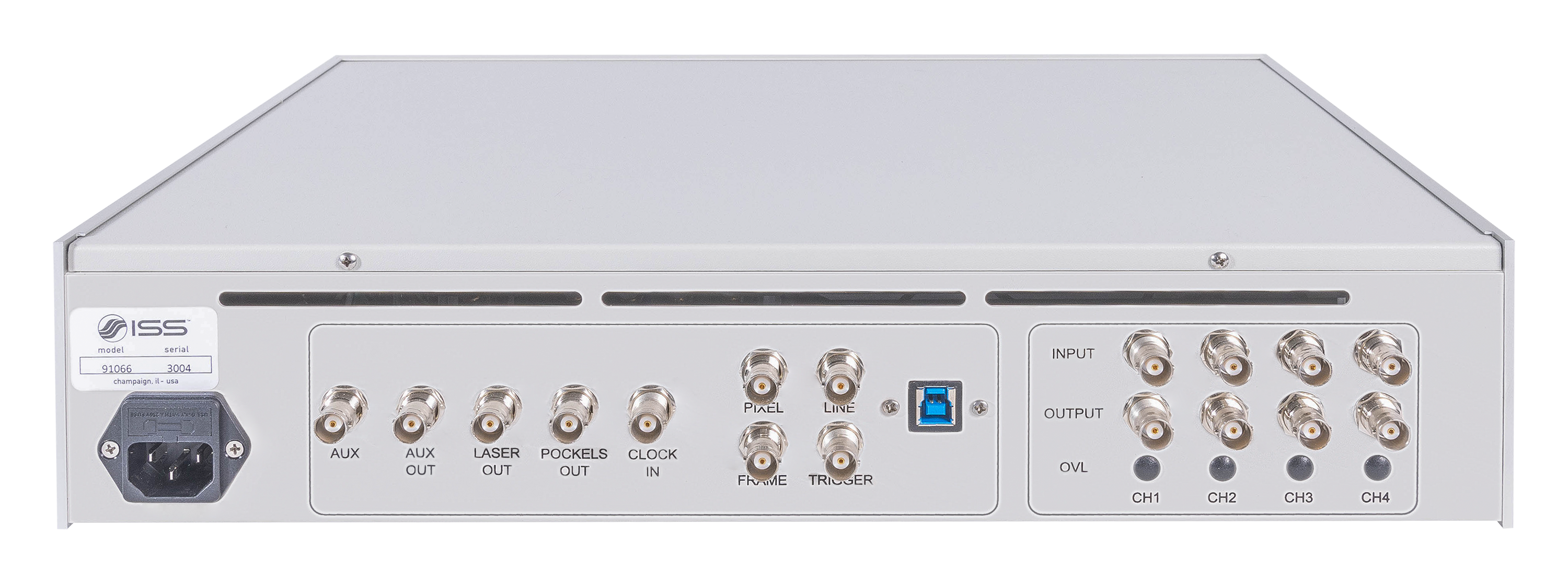
How FastFLIM Works in an Instrument
The signal from the detectors is directed to the FastFLIM unit. The synchronization of the acuisition with the XY position of the laser on the sample is provided by the FRAME/LINE/PIXEL CLK signals coming from the controller of the scanning mirrors unit.