Overview of Intensity Controller
Control the laser power diverted into the microscope by placing the Intensity Controller in front of the laser. The unit includes a fine-step, computer-controlled, rotating half-wave plate positioned in front of a fixed Glan-laser calcite polarizer. The half-wave plate rotates the plane of polarization of the input laser beam; only the vertical component is passing through the polarizer while the rejected portion is absorbed by a beam dumper. The intensity of the beam vertical component is finely controlled.
Compatible with Q2, and PL1.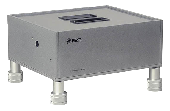
Theory
The vertically-polarized laser beam, first encounters the half-wave-plate that rotates its plane of polarization prior to entering into the fixed polarizer: the wave-plate is mounted on a computer-controlled rotating stage. The achromatic zero-order wave-plate consists of two different birefringent crystals: crystalline quartz and magnesium fluoride (MgF2), in an air-spaced design for high power; achromatic quartz MgF2 wave-plates offer excellent retardation accuracy over broad wavelength. It is a zero-order µs wave-plate; the thickness of this plate is such that the difference in phase between the ordinary and extraordinary axis of the light beam passing through it is exactly half a wavelength. The zero order assures that the property is maintained over a broader range of wavelengths. When rotating the wave-plate by φ degrees, the polarization of the output beam is rotated by 2φ degrees. That is, full control of the intensity is achieved by rotating the wave-plate in the range 0 - 45°. When the wave-plate is rotated, the intensity at the output of the polarizer is regulated according to the Malus' law:
I = I0 cos2 θ
where I0 is the intensity of the light beam prior to impinging onto the polarizer and θ is the angle between the polarization of the incoming beam (direction of the electrical field) and the axis of the polarizer. The intensity is at its maximum when the polarization of the beam is aligned with the axis of the polarizer; it is null for θ = π / 2 when the polarizer axis is perpendicular to the polarization of the incoming beam. With respect to the angle of rotation of the wave-plate, the intensity at the output is:
I = I0 cos2 2θ
The P component passes through with minimal loss; the S component is dumped outside the optical axis.
Product Specifications for Intensity Controller
Polarizer
Diameter
- 25.4 mm
Material
- Calcite
Wavelength Range
- 650 - 1000 nm
Extinction Ratio
- Tp/Ts > 100,000:1, 400 - 1064 nm, unpolarized input
Transmission
- Tp > 92%, polarized input, with broadband AR coating; Tp > 95%, polarized input
Damage Threshold
- 500 W/cm2 CW, 4 J/cm2 with 10 ns pulses, typical
Wavefront Distortion
- ≤ λ/4 at 632.8 nm over full aperture
Acceptance Angle
- Wavelength dependent, from 4° full angle at 441.6 nm to 1° full angle at 1064 nm
Waveplate
Diameter
- 25.4 mm
Wavelength Range
- 650 - 1000 nm
Material
- Crystalline quartz and magnesium fluoride (MgF2), in air-spaced design
Retardation
- λ/2
Retardation Accuracy
- From ±λ/50 to ±λ/100
Unit
Control
- USB
Height Adjustability
- 105 - 140 mm
Power
- 110 - 240 V
Dimensions
- 254 x 292 mm
Maximum allowed laser power versus beam diameter
| Beam Diameter (mm) | 5 | 4 | 3 | 2 | 1 |
| Laser Power (W) | 100 | 64 | 36 | 16 | 4 |